The relationship between Blend air door actuators and automotive HVAC systems
Whether in the heat or cold winter, passengers can always enjoy a comfortable car environment through the car's heating and cooling system. In different types of vehicles, the complexity and degree of automation of these heating, ventilation and air conditioning (HVAC) systems are also different. Economical cars may require the driver to manually turn the knob to control the temperature, while in high-end vehicles, the temperature in the car and the humidity and quality of the air can be automatically controlled at the same time through sensors.
air flow
Regardless of the type of vehicle, the automotive HVAC system needs to exchange air and change its temperature, humidity and quality in the process.
Let us look at the principle of air flow. Air can be drawn into the system from outside or inside the cabin. It can also enter the HVAC system through an evaporator or heat exchanger for regulation; the conditioned air is distributed throughout the cabin to keep the passengers' feet warm or prevent the windshield from fogging.
There are many ways of air flow: from the outside to the evaporator to the windshield, or from the inside to the heat exchanger to the vents at the bottom of the car. So how does the HVAC system control the air flow?
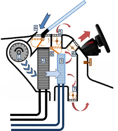
Figure 1 shows a side view of the HVAC system. Key components are marked with numbers, and arrows indicate the direction of air flow. Parts 4 to 8 in Figure 1 show damper actuators. The orange dotted line represents the area where the damper moves, and the orange solid line represents the damper. The number of damper actuators in an HVAC system depends on the overall complexity of the system—single-zone or multi-zone HVAC.
Figure 1: Automotive HVAC consisting of eight components: 1 = blower, 2 = evaporator, 3 = heater, 4 = intake damper, 5, 6 and 7 = air distribution damper, 8 = air mixing damper


.png)
